- #ARDUINO NANO PINOUT FUNMOVE HOW TO#
- #ARDUINO NANO PINOUT FUNMOVE .EXE#
- #ARDUINO NANO PINOUT FUNMOVE INSTALL#
- #ARDUINO NANO PINOUT FUNMOVE SERIAL#
- #ARDUINO NANO PINOUT FUNMOVE CODE#
So, you should use an external power source. Working with insufficient power supply may damage the display. You can power up the Nextion display directly from the Arduino 5V pin, but it is not recommended.

Here’s how you should wire the Nextion display: Nextion These pins are labeled at the back of your display, as shown in the figure below. You just need to make four connections: GND, RX, TX, and +5V. Wiring Nextion Display to the ArduinoĬonnecting the Nextion display to the Arduino is very straightforward. Now, you are ready to start experimenting with the Nextion display with Arduino UNO.

#ARDUINO NANO PINOUT FUNMOVE SERIAL#
Change line 37, so that you have the following: #define nexSerial Serial Comment line 32: //#define dbSerial Serialĥ. Comment line 27, so that it stays as follows: //#define DEBUG_SERIAL_ENABLEĤ.

There should be a NexConfig.h file – open that file.ģ. Open the ITEADLIB_Arduino_Nextion folderĢ. To make it work for Arduino Uno, you need to do the following:ġ. This library is configured for Arduino MEGA2560 by default.
#ARDUINO NANO PINOUT FUNMOVE INSTALL#
Follow the next steps to install the library:
#ARDUINO NANO PINOUT FUNMOVE .EXE#
exe file.īefore getting started, you also need to install the Nextion libraries for Arduino IDE. Go to h ttps:///, select the Resources tab, Download > Nextion Editor and install Nextion Editor. To get started with Nextion, first you need to install Nextion Editor. You can check Maker Advisor website to get your Nextion display at the best price – just click the links below: Additionally, this is the most used size, which means more open-source examples and resources for this size. If you’re just getting started with Nextion, we recommend getting the 3.2” size which is the one used in the Nextion Editor examples (the examples also work with other sizes, but you need to make some changes). The best model for you, will depend on your needs. has larger flash capacity and larger CPU clock.The Nextion enhanced has new features when compared with the basic model: You can grab a Nextion basic model, or a Nextion enhanced model. We have the 2.8” Nextion display basic model, that is shown in the following figure. To design the GUI, you use the Nextion Editor, in which you can add buttons, gauges, progress bars, text labels, and more to the user interface in an easy way. So, it works with any board that has serial capabilities like Arduino, Raspberry Pi, ESP8266, ESP32, and so on. The Nextion communicates with any microcontroller using serial communication at a 9600 baud rate. The Nextion has a built-in ARM microcontroller that controls the display, for example it takes care of generating the buttons, creating text, store images or change the background. There are several Nextion display modules, with sizes ranging from 2.4” to 7”. It is a great solution to monitor and control processes, being mainly applied to IoT applications. Nextion displays are resistive touchscreens that makes it easy to build a Graphical User Interface (GUI). Nextion is a Human Machine Interface (HMI) solution.

If you want to see different Nextion displays and find the best price, go to Maker Advisor to read our guide. We’ll also make a simple graphical user interface to control the Arduino pins.
#ARDUINO NANO PINOUT FUNMOVE HOW TO#
We’re going to show you how to configure the display for the first time, download the needed resources, and how to integrate it with the Arduino UNO board. Output:Īfter successful uploading of the code, try pressing and releasing the button, the LED glows if the button is pressed and gets off when the button is released.This post is an introduction to the Nextion display with the Arduino. const int BUTTON = 4 // Naming switch button pin const int LED = 3 // Namin LED pin int BUTTONstate = 0 // A variable to store Button Status / Input void setup ( ) 5.
#ARDUINO NANO PINOUT FUNMOVE CODE#
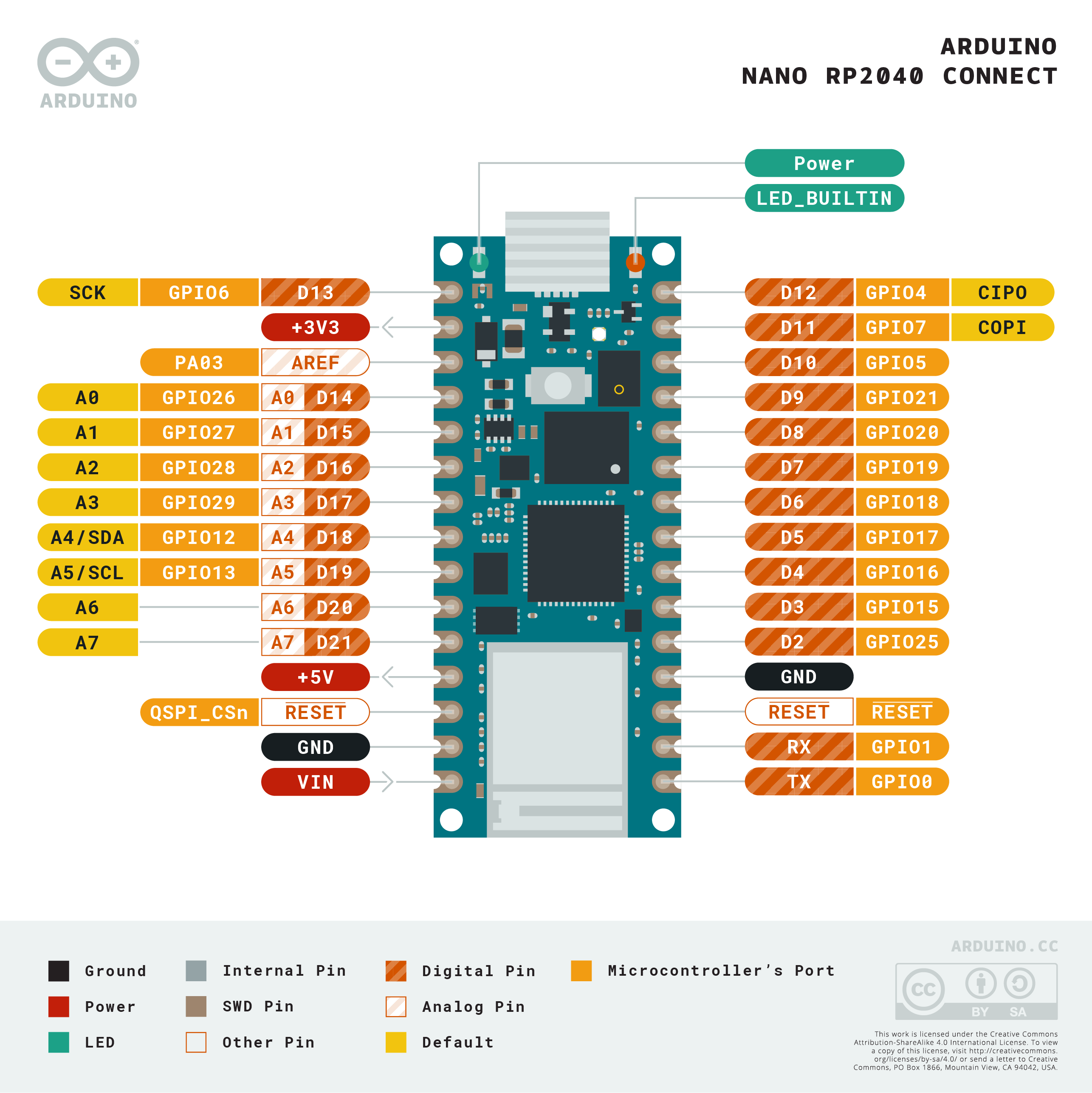
This code has a simple function to perform, if Button is pressed glow the LED. You may download codes (Arduino Sketch) from here. Once we are done with circuit part, here is our programme to this circuit. Thus this tutorial is for both digital input and digital output. That input is read by Arduino Nano board and decision is taken accordingly. In this tutorial we are taking digital input from a push button switch. Introduction:Ī step by step illustrated basic tutorial for Arduino Nano. This input is processes by Arduino Nano and it send digital command to attached LED. Digital input is taken through push button and that is detected by Arduino Nano. This tutorial explains Digital input and digital output.


 0 kommentar(er)
